Why is it worth designing a rack yourself?

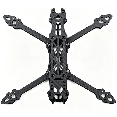
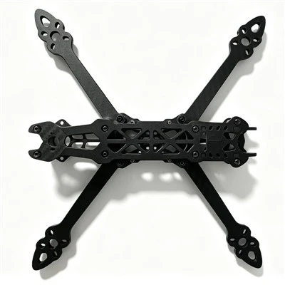
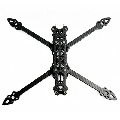
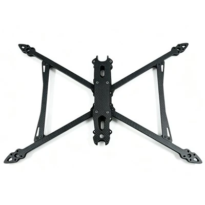
The frame of an FPV racing drone may look like just a few carbon fiber plates and some metal pillars, but it is the fundamental skeleton of the entire aircraft. The frame determines how large a propeller you can install, how the flight controller is mounted, where the antenna extends from, how troublesome the repairs are after a crash-and the base weight of the entire machine before any electronic equipment is mounted. Increasing the arm length of a frame by just one inch is enough to significantly change the flight stability.
There is a wide variety of commercial frames on the market, but there are always some needs that off-the-shelf products cannot meet: you might want a low-profile frame specifically adapted for a certain HD camera, or need an extremely short wheelbase to fly narrow indoor tracks. Designing your own frame means you have complete control over every dimension and every mounting hole. More importantly, the entire process from CAD to the physical object is itself the best way to understand the structural principles of an aircraft.
1. First, figure out what you want to do.
Before opening CAD, write down the requirements clearly. Doing this step solidly can save a lot of rework time later.
Core parameter list:
Propeller size:
Determines the wheelbase range. A 5-inch quad typically corresponds to a 210–225mm wheelbase, a 3-inch quad is about 135–150mm, and a 7-inch long-range frame requires 280–300mm.
Flight controller/ESC mounting hole positions:
Commonly 20×20mm or 30.5×30.5mm. 5-inch frames generally use 30.5×30.5mm, while those under 3 inches mostly use 20×20mm.
Motor mounting hole spacing:
Most 5-inch motors use 16×16mm M3 holes, while some also use 19×19mm. Small-sized motors (such as 1404) commonly use 12×12mm.
Camera system:
Micro camera (19mm wide) or full-size camera? What is the required camera tilt range? If it is the DJI O3/O4 Air Unit, the size and heat dissipation requirements are completely different from analog video transmission.
Battery installation method:
top-mounted or bottom-mounted? Battery strap width is 15mm or 20mm?
Arm scheme:
Integrated baseplate or independent replaceable arm? Independent arms have low maintenance costs, but the mainboard needs to be designed with a slot to fit the arm.
The geometric configuration of the rack must also be determined in advance:
True X:
All four arms radiate from the center at 45°, with an even propeller wash distribution and symmetrical yaw, making it the standard layout for freestyle and racing.
Squashed X:
The angle between the forearms is asymmetrical, allowing the blades to be completely excluded from the camera's field of view, making it suitable for film and television rigs that require a clean shot.
Deadcat:
The rear arms flare out significantly and the front arms narrow, providing the cleanest camera view, commonly found on Cinewhoops and some long-range models, at the cost of a slight decrease in flight efficiency.
Stretched X:
The front-to-back distance is greater than the left-to-right distance, improving forward flight efficiency and pitch control, suitable for long-range and racing.
Preset a wheelbase conversion formula: In a True X layout, the side length of the motor layout rectangle = wheelbase ÷ 1.4. For example, a 210mm wheelbase corresponds to a rectangle side length of about 150mm. The diagonal distance from motor to motor for a 5-inch frame should be set to 220–230mm.
II. Choose a handy CAD tool
III. Key Steps of CAD Modeling
Step 1: Create component reference models. Do not start by drawing the frame outline right away. First, create a simplified model for each of the flight controller stack, motors, camera, antenna, and battery, retaining only the mounting hole positions and the dimensional accuracy of the outer profile, without needing detailed appearance. Many manufacturers provide STEP files that can be downloaded and imported directly. The purpose of these reference models is interference checking-to ensure that your frame design will not conflict with the actual components.
Step 2: Draw the main sketch. The main sketch defines the basic geometry of the frame. Draw the center positions of the four motors on the top surface, draw the centerlines of the arms connecting to the center body, and mark the angle reference lines for the camera mounting plane. Set the wheelbase, arm width, motor hole spacing, and propeller diameter as user parameters. This way, when you want to adjust the wheelbase or arm width later, changing a single parameter will update the entire model.
Step 3: Determine the clearance between the motor mounts and the propeller discs. Draw the mounting hole circles and the motor mount outlines at the center positions of the four motors. At the same time, draw the rotation trajectory circle of the propeller tips, and leave a safety clearance of at least 5mm between the propeller tips and any part of the frame.
Step 4: Draw the arms and the center block. The integrated baseplate is the simplest, drawing a rectangle directly from the motor mount to the center block. The independent arm solution requires drawing the arm's mating slot and bolt holes on the main plate first, and then modeling the arm parts separately. The design of the mating slot is much more important than a simple bolt connection-it distributes the impact load across the entire contact surface of the slot, rather than concentrating it around the bolt holes.
Step 5: Plan the installation positions for the electronic devices. The FPV camera is usually secured using vertical plates on both sides or a 3D-printed mount. The installation positions of the receiver and the video transmitter antenna directly affect signal performance-the antenna should be kept as far away from the carbon fiber plates and motor wires as possible. The USB port of the flight controller requires a reserved opening or sufficient operating space. The video transmitter needs to consider heat dissipation, and the surrounding area should not be completely enclosed.
Step 6: Chamfering and rounding. This step is not "beautification", but structural engineering. The junction between the arms and the center body, the bottom of the motor mounts, and all internal corner positions must be rounded. The minimum radius is 2–3mm. Stress concentration at sharp corners can easily cause a carbon plate to break during the first crash, whereas the same design with rounded corners can improve durability several times over.
IV. Material Selection and the Particulars of Carbon Fiber
Carbon fiber remains the mainstream material for frames because its stiffness-to-weight ratio is unrivaled. The standard carbon plate thickness for a 5-inch FPV drone frame is 2mm for the bottom plate, 1.5–2mm for the top plate, and 4–6mm for the arms.
But carbon fiber is not a homogeneous material. Its strength depends on the direction:
Twill weave (2×2 twill):
The fibers are interwoven diagonally, dispersing the load along the diagonal direction upon impact, providing the best impact resistance. Most high-quality frame arms use this weave.
Plain weave (1×1 plain weave):
A checkerboard pattern that is stiffer at the same thickness because the fiber arrangement is more direct. However, the stress concentration at the 90° intersection makes it more prone to clean breaks under direct impact. It is suitable for use in the center plate area where the requirement for stiffness is higher than for impact resistance.
Unidirectional (UD fabric):
All fibers are aligned in the same direction, extremely stiff along the fiber direction, but extremely weak in the perpendicular direction. Pure UD arms will split along the fiber direction under impact and are rarely used alone.
When CNC cutting, you must confirm the weave direction with the manufacturer. Carbon fiber is strongest along the fiber length direction, so the high-stress areas of the arm should have the weave direction parallel to the arm's axis. If the weave of the carbon plate is cut at 45°, the strength of the arm will be greatly reduced.
3D printing as an alternative: PETG is suitable for beginners, while PA6-CF (carbon fiber reinforced nylon) is currently the strongest printing material, with a stiffness close to aluminum alloy and an impact resistance exceeding most plastics. However, the strength of the printed parts highly depends on the wall thickness rather than the infill rate. The arm requires at least 4–6 wall layers; 6 wall layers combined with a 12mm arm width and 4mm thickness make the cross-section practically solid, which is necessary to withstand the motor thrust load. The 3D-printed camera mount and motor dampeners should use TPU-its flexibility can absorb high-frequency vibrations and eliminate the rolling shutter effect in the footage.
V. Most Common Mistakes Made by Beginners
Error 1: Thinking "thicker is stronger". A poorly designed 6mm arm, without a interlocking structure, will break faster than a well-designed 4mm arm. Thickness is just one variable of stiffness; load distribution and interlocking design are equally critical.
Error 2: Ignoring the conductivity of carbon fiber. Carbon fiber is conductive. If the circuit boards of the flight controller, ESC, and VTX directly touch the edges of the carbon plate, or if the insulation layer of the motor wires is worn through as they pass through the holes in the carbon plate, it will cause a short circuit. All electronic equipment mounting points should have insulation measures, or protective sleeves should be added to the edges of the carbon plate.
Error 3: Insufficient wall thickness around the motor mount. The M3 motor screws cause significant stress concentration on the motor mount. The wall thickness around the motor mount should be increased to 4–5mm, and 100% infill should be used when printing this area.
Error 4: Sending to cutting without physical verification. Printing out the design drawing and measuring the hole positions with a ruler is the cheapest verification method. A flight controller hole that is off by 0.5mm means the entire carbon fiber plate is scrapped. Overlaying the design files of different parts to check hole alignment is also a necessary step.
Error 5: Not sharing, not asking for advice. There are many pilots with engineering backgrounds in the FPV community who are very willing to help you review your designs. Posting a few design screenshots in forums or communities often yields useful feedback regarding structural weak points.
VI. From Document to Physical Object
CNC cutting service is the most common manufacturing method. The advantage of professional FPV frame CNC manufacturers (such as Armattan Productions) is that they understand FPV drones-they know how to align the carbon fiber weave direction and which hole positions require high-precision tolerances. The disadvantage is that international shipping and processing cycles usually take several weeks. Local CNC services are faster, but they may not be familiar with the manufacturing requirements of drone frames, requiring you to proactively communicate the weave direction and tolerance standards.
In terms of cost, the CNC cutting fee for a 5-inch carbon fiber frame (excluding materials) is usually in the range of dozens to over a hundred RMB, and it will be higher for 7 inches and above. If you are only making one or two prototypes, you can also consider using a desktop CNC or laser cutting acrylic plates for size verification, and then cutting the carbon fiber after confirming there are no errors.
Design file delivery format: Most CNC manufacturers accept DXF (2D profile) or STEP (3D model) files. In 2D profile files, it is necessary to distinguish between cutting lines and drilling positions, and the hole diameters and tolerances must be clearly marked. If your design includes independent machine arms, export each part separately.
Conclusion
FPV frame design does not require a degree in mechanical engineering, but it does require patience and respect for detail. From defining requirements and creating parametric sketches to handling the anisotropy and stress concentrations of carbon fiber-every step is training your understanding of aircraft structures. The first design iteration is highly unlikely to be perfect, but the cost of one print validation plus one CNC cut is far lower than buying multiple off-the-shelf frames for trial and error. And when you fly your own designed frame in the sky for the first time, that feeling is unlike flying any off-the-shelf model.
FAQ
Q: Do I need a mechanical engineering degree to design an FPV drone frame?
A: No. You need basic CAD skills, patience, and an understanding of key structural principles such as stress risers, mounting hole spacing, and carbon fiber weave direction.
Q: Is 2D CAD enough for FPV frame design?
A: Yes, for simple carbon plate frames, 2D CAD is enough. Use 3D CAD if you want to design camera mounts, canopies, stack spacers, or check interference between parts.
Q: Which CAD software is best for beginners?
A: Fusion 360 is popular and free for personal use. Onshape works in a browser and is good for collaborative design. QCAD is a simple free 2D option.
Q: How do I calculate the motor layout for a True X frame?
A: For a True X frame, divide the wheelbase by 1.4 to get the side length of the motor layout rectangle. For example, a 210mm wheelbase gives about 150mm per side.
Q: What is the difference between True X, Squashed X, Deadcat, and Stretched X?
A: True X has symmetrical 45-degree arms. Squashed X adjusts front and rear arm angles to keep props out of view. Deadcat widens the rear arms for the cleanest camera view. Stretched X makes the frame longer front-to-back for forward-flight efficiency.
Q: Why does carbon fiber weave direction matter?
A: Carbon fiber is strongest along the fiber length. On arms and other high-stress areas, the weave should run parallel to the arm axis. A 45-degree weave can significantly reduce strength.
Q: What is the basic workflow from idea to finished frame?
A: Define requirements, create a parameterized sketch, add electronics reference models, design motor mounts and arms, plan electronics mounting, add fillets, validate dimensions, export DXF/STEP, then send to CNC.