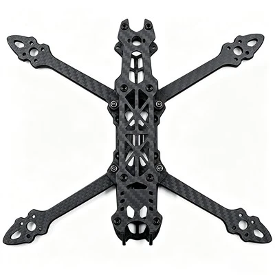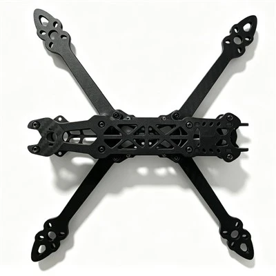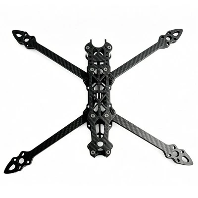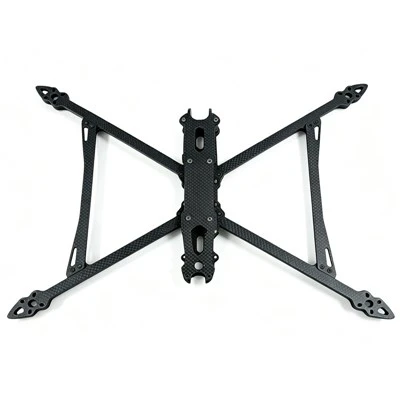
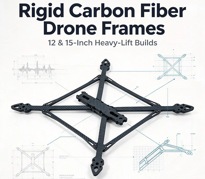
When you move from a 5-inch freestyle quad to a 12-inch or 15-inch heavy-lift platform, the dominant engineering problem changes. On a 5-inch build, the frame is rarely the limiting factor: arms are short, motors spin fast, and modern flight controllers filter high-frequency noise with relative ease. At 12–15 inches, the lever arms are long, the props turn slowly, and the payload is measured in kilograms rather than grams. The frame stops being a mounting plate and becomes the structural backbone that determines whether the aircraft is tunable, efficient, and safe.
The failure mode is not usually a dramatic snap in mid-air. It is more often a slow erosion of control quality: low-frequency resonance that software cannot filter without introducing lag, arm deflection that misaligns thrust vectors under torque, and joints that loosen over time and shift the frame's modal behavior unpredictably. Understanding why rigidity matters-and where rigidity alone is not enough-is the difference between a platform that flies smoothly and one that fights its own structure.
1. Rigidity vs. Damping: Two Different Jobs
A common oversimplification is that "a stiff frame damps vibration." Rigidity and damping are not the same property. Rigidity controls where the frame's natural frequencies sit; damping controls how quickly vibration energy dissipates once excited.
Carbon fiber has an excellent stiffness-to-weight ratio, but its intrinsic material damping is modest. A rigid frame helps primarily by pushing the arm-bending and torsion modes to higher frequencies, ideally above the bandwidth where PID loops and gyro filters are most active. A flexible arm that resonates at 120–180 Hz can sit directly in the PID correction range and produce visible oscillation; a stiff arm that resonates above 300 Hz is far easier for Betaflight's default filtering to attenuate.
Damping, on the other hand, comes from interfaces and additions: the micro-slip between clamped arm and center plates, the friction in bolted joints, the elastomer in a flight-controller mount, and the mass distribution of the build. This is why a well-designed frame is not simply "as stiff as possible." It is a structure that puts rigidity where stiffness raises resonance out of the control band, and puts damping where joints and mounts can dissipate the residual energy.
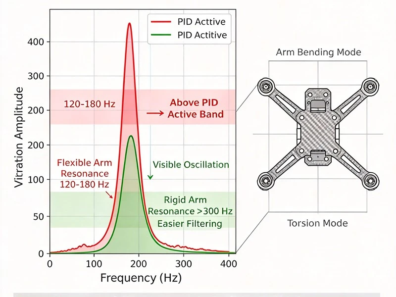
Practical implication: If the gyro log shows a broad low-frequency peak that moves with throttle, the problem is structural resonance, not filter settings. No amount of PID tuning will fix a mechanical resonance; the frame geometry, arm thickness, or joint preload must change.
2. Arm Thickness, Resonance Frequency, and the Drag Penalty
Arm thickness is the single most direct lever for bending stiffness, but it is not a free parameter. Thicker arms raise resonance frequency and crash survival, yet they also increase frontal area and drag.
| Frame class | Typical arm width | Typical arm thickness | Resonance tendency | Trade-off |
| 5-inch racing | 10–12 mm | 5 mm | 300–400 Hz, stiff and fast | Low drag, limited crash margin |
| 5–7-inch freestyle | 12–15 mm | 6 mm | 220–320 Hz, tunable | 6 mm arm ≈44% more frontal area than 5 mm; at 120 km/h this can cost 8–12 A extra draw |
| 12–15-inch cinematic/heavy-lift | 14–18 mm+ | 6–10 mm+ | goal: push bending modes above the PID-active band | Thickness raises stiffness but adds weight and drag; real 15-inch heavy frames often use 10 mm arms |
The original "6–8 mm is the right range for 12–15 inches" is directionally useful for cinematic vibration isolation, but real heavy-lift products often go thicker. The HGLRC MY15 uses 10 mm carbon arms on a 635 mm wheelbase, and the Heavy Line F415 specifies 10 mm arms for payloads up to 5 kg. The lesson is not a single number; it is that arm thickness must scale with wheelbase, expected torque, and landing energy, and that beyond a certain point the drag and weight cost becomes the binding constraint.
3. Flat Plates vs. Tubular Arms: Stiffness per Gram, and What It Costs You
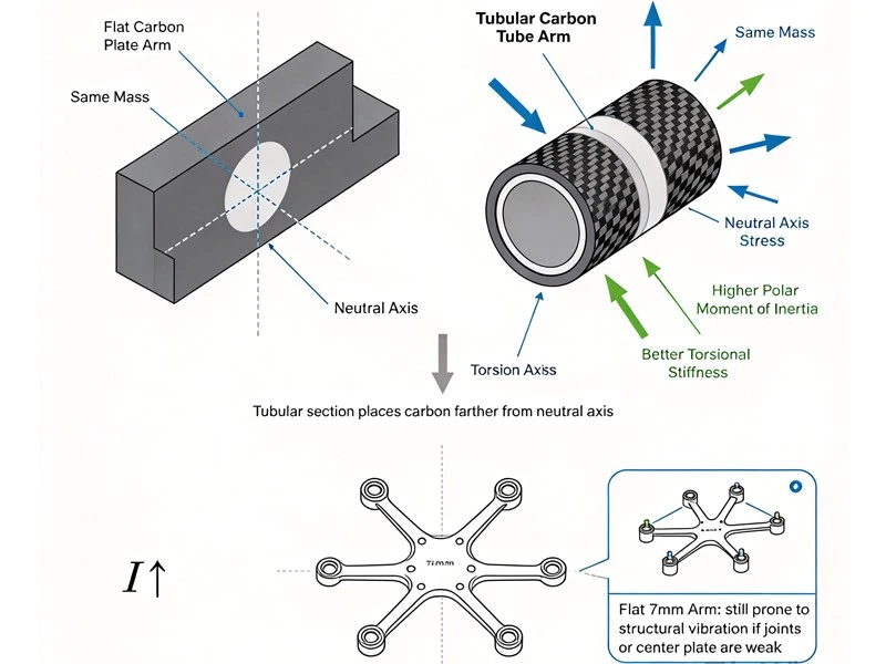
For a given mass, a tubular cross-section distributes material farther from the neutral axis than a flat plate, giving it a higher polar moment of inertia and better torsional resistance. In practice, users who switch from flat arms to carbon tubes on large builds often report a dramatic reduction in low-frequency vibration, while flat arms of 7 mm thickness can still exhibit structural vibration if the joint design or center-plate stiffness is inadequate.
But tubes are not a universal upgrade. They complicate motor-mount alignment: if the motor plane is not level, the thrust vector tilts and yaw imbalance appears. Assembly is more demanding, and crash repair is less straightforward than swapping a flat arm. Flat plates remain dominant in commercial FPV because they are easier to manufacture, cheaper to replace, and-when properly dimensioned and well-preloaded-can be sufficiently rigid.
Selection rule:
4. Torque, Thrust-Vector Integrity, and the Limits of the "3115 Standard"
Large props demand torque, and torque reacts against the frame. When an arm twists, the thrust vector is no longer purely vertical. The flight controller sees an uncommanded roll or pitch component and corrects it with more motor differential, which costs current and generates heat.
The structural requirement is straightforward: the arm and its mounting joint must resist torsion well enough that the motor plane stays close to its intended orientation under peak torque. This is why torsional stiffness, not just bending stiffness, is a design objective for heavy-lift frames.
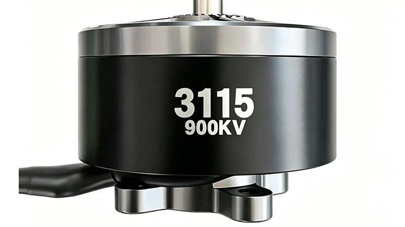
The "3115 motor" deserves a correction. A 3115 stator is a legitimate high-torque motor, but its natural habitat is closer to 10–12-inch propellers on 6S–8S, where it can produce multi-kilogram thrust per motor. For 15-inch heavy-lift platforms, the common stator classes are larger-4214, 4315, 5215, and 5315-and KV selection follows the voltage system: roughly 280–400 KV on 12S, 350–420 KV on 8S, and 400–600 KV on 6S. Using a 3115 as the default "standard" for a 15-inch build is like specifying a mid-size sedan engine for a light truck: it can move the vehicle, but it is not the torque reserve the chassis was designed around.
Power-system pairing logic:
| Voltage | 15-inch KV range | Typical stator class | Structural implication |
| 12S | 280–400 KV | 5215–5315 for heavy payload | Highest torque per arm; torsional stiffness and joint preload are critical |
| 8S | 350–420 KV | 4315–5215 | Balanced torque and weight; 10 mm-class arms common |
| 6S | 400–600 KV | 4214–4715 for light-load endurance | Lower voltage, higher current; check ESC and wiring margins |
5. Landing Inertia, Delamination, and Post-Crash Structural Honesty
Kinetic energy scales with mass. A 5-inch quad at 600–800 g can hit grass and often survive with a bent prop. A 15-inch platform at several kilograms carries an order of magnitude more energy into the same impact. The frame's job is not to be infinitely strong; it is to absorb and distribute impact without hidden internal damage.
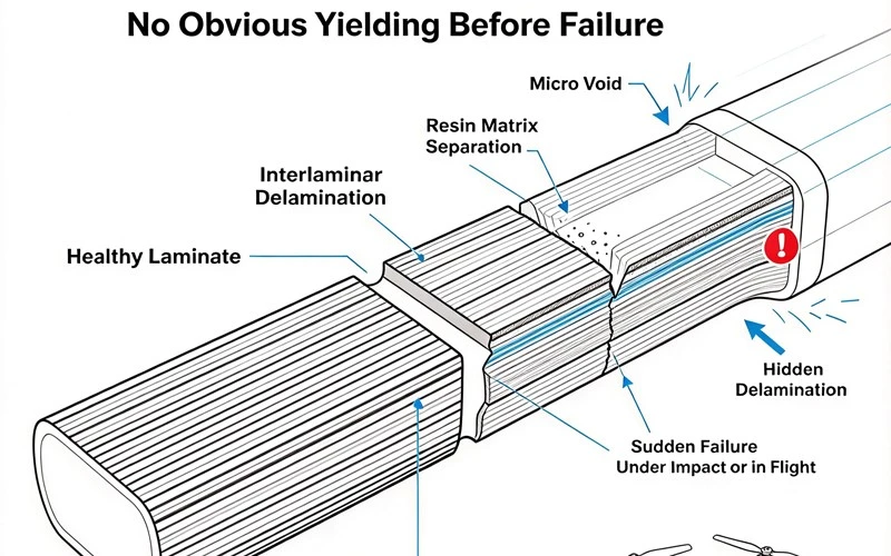
Carbon fiber fails differently from metal. It does not yield visibly before breaking. The dangerous failure mode is interlaminar delamination: the resin matrix between carbon layers separates, often starting from micro-voids created during curing. A delaminated arm can look intact externally and then fail on the next moderate impact-or in flight.
This is where frame quality becomes a maintenance issue, not just a purchase decision. Premium laminates using T700/T800 prepreg and controlled cure have far fewer voids than budget press-cured T300-equivalent sheets; the difference shows up not in the first flight but in the tenth crash. A simple field check: tap the arm with a screwdriver. A clean, sustained ring suggests laminate integrity; a dull thud suggests separated layers.
Post-crash inspection minimum:
Press each arm along its length; compare flex to a known-good arm. A sudden increase in compliance is a red flag.
Inspect arm roots and motor-mount areas for whitish edges, fuzzy fibers, or hairline cracks.
Check bolt torque at arm-to-plate joints. Loosened bolts change resonance characteristics and can trigger sudden PID instability.
If delamination spans more than roughly 25% of an arm's surface, replace the arm rather than repairing it.
6. A System-Level Build Logic, Not a Single "Rigid Frame" Rule
A rigid frame is necessary but not sufficient. The platform flies well only when frame stiffness, joint design, propulsion matching, and vibration isolation are chosen together.
Build decision sequence for 12–15 inches:
Define payload and landing environment first. A 2 kg cinematic payload with frequent hard landings needs a different arm thickness and joint strategy than a 5 kg endurance platform that mostly lands softly.
Choose wheelbase and prop size; then choose motor stator and KV from the voltage system. Do not start from a motor number and force the frame to compensate.
Select arm cross-section and thickness to place resonance above the PID-active band, not simply "as thick as possible." Use flat thick arms when weight, cost, and repairability dominate; consider tubes when torsional load and long levers dominate, and budget for precise motor-mount alignment.
Design the joints as structural elements. Clamped arms with adequate preload, friction damping at plate interfaces, and thread-locking on critical fasteners are not accessories; they are part of the stiffness system.
Treat vibration isolation as a separate layer. A rigid frame and a soft FC mount are complementary, not contradictory. The frame raises structural resonance; the mount attenuates what remains before it reaches the gyro.
Inspect for delamination after every hard hit. Structural honesty after a crash is more valuable than a stiffness specification on paper.
A 12- or 15-inch heavy-lift FPV platform is not a scaled-up 5-inch quad. It is a structure in which arm stiffness, joint preload, resonance placement, propulsion torque, and impact energy are coupled. Rigid carbon fiber is the right foundation-but only when it is understood as one part of a structural system, not as a single specification that solves every flight problem.
FAQ
Q: How thick should carbon arms be on 12/15-inch frames?
A: 6–8 mm is a starting range for moderate payloads; 15-inch, 5 kg-class builds commonly use 10 mm-class arms. The goal is not a fixed number but pushing arm bending resonance above the PID-active band while controlling weight and frontal area.
Q: Are tubular carbon arms better than flat plates?
A: Tubes offer higher torsional stiffness per gram but complicate motor-mount alignment and joint design. Most FPV frames still use thick flats for simple manufacturing, cheap replacement, and easy crash repair; tubes suit very long-lever, torsion-dominated builds with precise alignment tooling.
Q: Why does low-frequency oscillation persist with aggressive filtering?
A: The cause is frame resonance, not filtering. Check the Blackbox spectrogram: throttle-dependent noise is motor/prop; a stationary narrow band is frame resonance. Fix priority: mechanical stiffening → arm-tip mass damping → fixed notch filter (last resort).
Q: Is a 3115 motor enough for a 15-inch heavy-lift platform?
A: A 3115 suits 10–12-inch props better. 15-inch heavy-lift commonly uses 4315, 4715, 5215, or 5315; KV follows voltage: ~280–400 KV on 12S, ~350–420 KV on 8S, ~400–600 KV on 6S. Motor torque reserve should match frame stiffness.
Q: Is a carbon arm still airworthy after a crash?
A: Tap test: a crisp "ting" is healthy; a dull "thud" suggests delamination. Twist test: creaking or more than 1–2 degrees of twist means separated layers. Replace if delamination exceeds 25% of arm surface area; do not repair.
Q: Does a very rigid frame get too heavy and hurt flight time?
A: There is a weight cost, but efficiency loss from arm deflection and resonance is usually more expensive. Concentrate stiffness at arm roots, motor mounts, and joints; trim weight from non-structural areas-not by compromising arm stiffness.