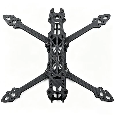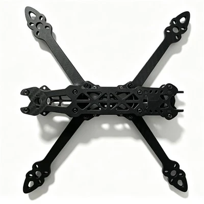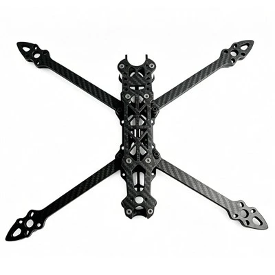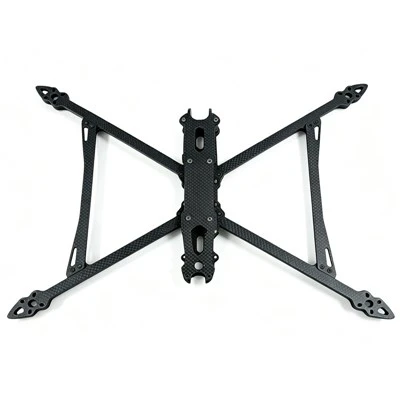
In the high-stakes world of FPV flight, your frame is far more than an aesthetic structural chassis. It functions as the physical dampening system for your flight controller, the armor for your electronic speed controllers (ESCs), and the mechanical link that translates motor torque into aerodynamic thrust. When an FPV quad clips a steel gate at 80 mph or carries a ten-thousand-dollar camera rig through high-velocity cinematic sweeps, the structural stress placed on the carbon plates is immense.
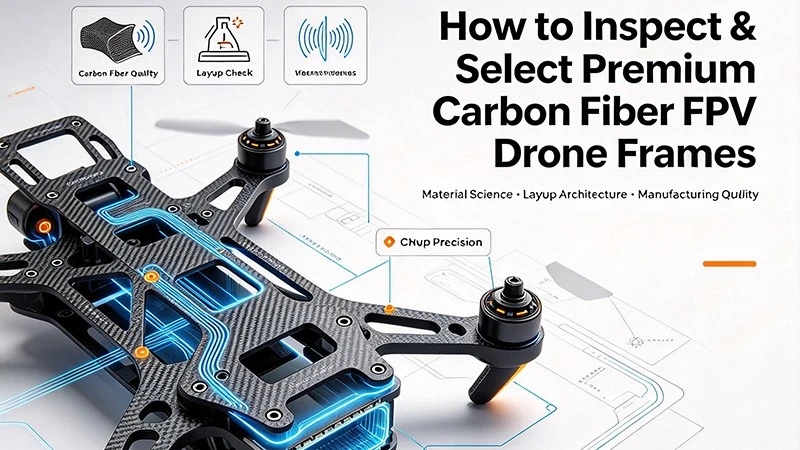
To the untrained eye, two carbon fiber frames look identical on a product listing page. Yet, beneath the surface matte finish lies a massive spectrum of manufacturing techniques, material compositions, and structural engineering layouts. Choosing a sub-par frame introduces low-frequency structural resonances, causes premature delamination during minor crashes, and generates continuous gyro noise that degrades flight performance. This engineering-grade guide details the material science behind high-quality carbon fiber, giving you the technical knowledge required to inspect, test, and select frames capable of surviving the ultimate torture tests.
1. Material Composition: The Hidden Fiberglass Threat
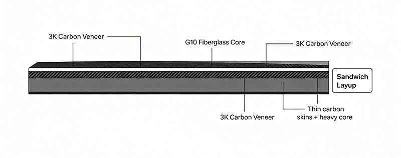
The first metric of quality is the purity of the raw composite sheet. Premium FPV frames are cut from solid 100% 3K Carbon Fiber sheetsbonded together with high-temperature epoxy resins. Budget manufacturers often cut production costs by using a highly deceptive material architecture known in manufacturing as a "sandwich layup."
The G10 Fiberglass Core Deception
To mimic high-grade carbon plates while slashing materials costs by up to 60%, factories layer a razor-thin decorative veneer of genuine 3K carbon cloth on the top and bottom exterior surfaces. The internal core, however, is packed with G10 fiberglass or low-grade composite filler scrap.
The Engineering Consequences
Fiberglass is significantly heavier and less rigid than pure carbon fiber, resulting in three severe operational failures:
- Elastic Structural Flex: Under high-torque maneuvers or sudden direction changes, the arms flex elastically. This physical distortion alters the motor thrust vectors relative to the flight controller's orientation.
-
Gyro Noise and Hot Motors: Frame flex introduces physical micro-oscillations. The flight controller's gyro interprets these oscillations as actual flight movement, forcing the PID loop to over-correct continuously. This results in prop wash handling failures, mid-flight shaking, and severely overheated motors.
-
Low Impact Resilience: Because the bonding layers between the carbon veneer and the fiberglass core are dissimilar materials, they exhibit vastly different thermal expansion and impact absorption properties. A sharp collision causes immediate internal shearing, cracking the plate from the inside out.
Diagnostic Field Testing
To identify a fiberglass core frame before building out your electronics, perform these two tests:
The Acoustic Ring Test:
Suspend the bare unmounted carbon plate by a string and tap it lightly with a metal tool. Pure, high-modulus carbon fiber produces a bright, high-frequency, crystal-clear metallic "ting." A frame filled with a fiberglass core absorbs the sound waves, yielding a flat, dull, short-lived thud.
The Digital Scale Metric:
Pure carbon fiber has a density of roughly 1.5 to 1.8 g/cm³, whereas G10 fiberglass is much denser, weighing around 2.0 g/cm³. If two identical 5-inch frames vary in weight by more than 10 to 15 grams without any variance in hardware, the heavier frame almost certainly utilizes a composite filler core.
2. Weave Architecture: Twill vs. Plain Weave Dynamics
Carbon fiber cloth used in FPV frame production is categorized by its tow rating-most commonly 3K, which represents 3,000 individual carbon filaments bundled into a single interwoven strand. How these strands are woven together determines the direction of the plate's structural resistance.
Plain Weave (1x1 Pattern)
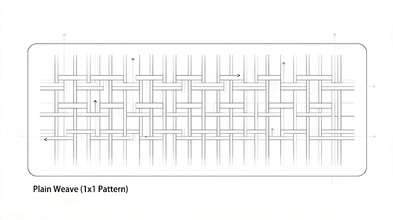
In a plain weave layout, each carbon strand passes over one perpendicular strand and directly under the next. This tight, symmetrical interlocking pattern creates a highly stable cloth with excellent weave uniformity.
- Advantages: It holds its shape perfectly during high-speed CNC milling, resulting in extremely clean cuts, minimal edge fraying, and highly rigid performance across flat planes.
- Best Used For: Top plates, bottom plates, camera mounting braces, and isolation stacks where uniform structural stability is paramount.
Twill Weave (2x2 Pattern)
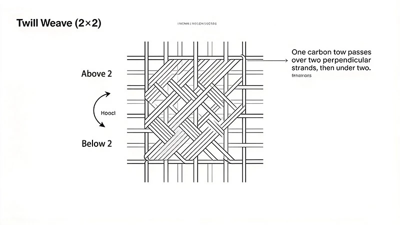
A twill weave features a pattern where one carbon strand passes over two perpendicular strands before dipping under two. This creates a highly recognizable diagonal pattern across the surface of the plate.
- Advantages: Because the strands have longer horizontal transitions, the weave contains less crimp (the bending of fibers over each other), allowing the natural tensile strength of the carbon filaments to remain uncompromised. Twill is far more effective at absorbing high-velocity kinetic energy and dispersing impact loads across a wider surface area.
- Best Used For: Thick frame arms, low-slung cinematic baseplates, and front bumpers that directly take the brunt of severe structural crashes.
3. Fiber Orientation and Quasi-Isotropic Stacking
Carbon fiber is highly anisotropic, meaning its structural strength exists almost entirely along the linear path of the fibers. A strand pulled lengthwise resists incredible forces, but pushed from the side, it shears easily. To make a durable drone frame, sheets must be engineered to resist forces from all 360 degrees of motion.
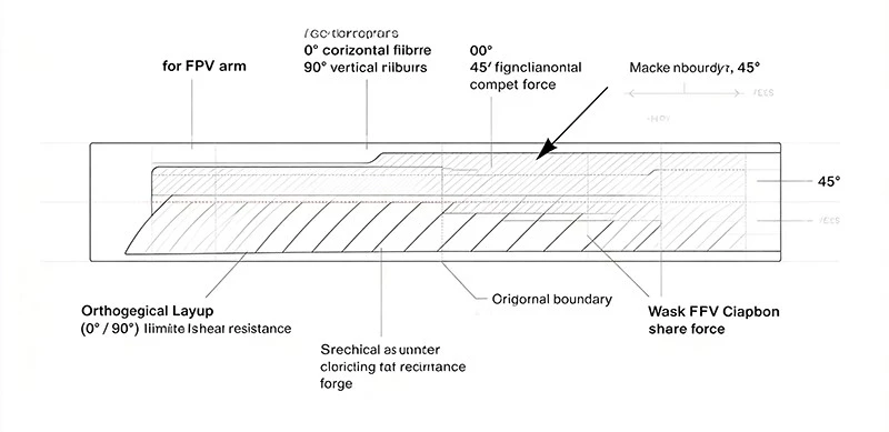
Orthogonal Cut Limitations (0°/90°)
Standard, budget carbon sheets feature layers stacked entirely at 0° and 90° angles. If a CNC machine cuts an FPV drone arm directly along the 0° axis, the arm is exceptionally rigid front-to-back. However, during a high-speed cornering impact, the crash force hits the arm at a 45° diagonal shear vector. Because there are no internal fibers running along that diagonal axis, the layers easily split apart along the resin lines.
Quasi-Isotropic Engineering (+45°/-45°/0°/90°)
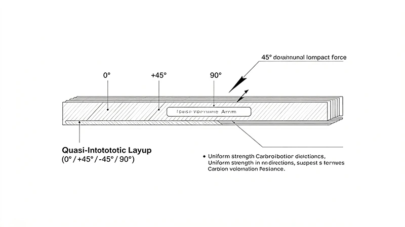
Premium FPV frames utilize high-end quasi-isotropic carbon sheets. These plates are engineered by meticulously stacking micro-layers of carbon cloth at alternating angular configurations: 0°, +45°, -45°, and 90°.
- The Result: When the drone arm is milled from this composite stack, it possesses uniform mechanical properties in every direction.
- Flight Benefit: A quasi-isotropic layup prevents high-frequency resonance waves from traveling down the length of the arm unimpeded. The cross-hatched fiber layers scatter internal vibrations, self-dampening the frame before the physical noise can ever reach your flight controller's gyro.
4. CNC Manufacturing Precision and Finishing Quality
Even the finest raw carbon sheet can be ruined by poor manufacturing precision. The tooling, speeds, and processing methods used during CNC milling dictate the long-term durability of the frame hardware.
CNC Bit Wear and Internal Delamination
Carbon fiber is intensely abrasive, wearing down industrial solid-carbide CNC router bits rapidly. When a factory runs dull bits to save on replacement tooling costs, the bit no longer slices cleanly through the carbon strands; instead, it punches and tears through them using brute force.
- Spotting the Issue: Inspect the inside edges of the arm cutouts and bolt channels. If you spot tiny frayed hairs, fuzzy white edges, or small structural separations between the layers, the bit was dull. These micro-tears allow environmental moisture, field dirt, and conductive carbon dust to enter the core, accelerating internal delamination every time you crash.
Factory-Engineered Chamfered Edges
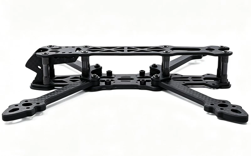
Raw cut carbon fiber leaves behind a sharp, razor-thin 90° corner edge. Top-tier FPV frames feature factory-machined chamfered (beveled) or radiused edges on all primary structural plates.
- Impact Dispersion: Beveling the edges removes high-stress focal points along the corners of the carbon plate. When an edge strikes a hard surface, the angled profile redirects the kinetic force outward rather than concentrating the energy on a single corner point that could split the sheet.
- Component Safety: Raw carbon edges act like razor blades under tension. During high-G maneuvers, a sharp edge can easily slice right through a battery strap, sending a LiPo battery flying mid-air. It also poses a constant abrasion hazard to exposed motor wires and silicone power leads. Factory chamfering rounds these edges down, ensuring your components remain completely safe.
Resin Optimization: Matte vs. High-Gloss Finishes
- The High-Gloss Mirage: High-gloss finishes are highly visual, but they are often used to mask flaws or heavy resin pools. A frame with excess resin is brittle, unyielding, and unnecessarily heavy.
- The Satin/Matte Standard: A premium satin or matte finish indicates that the plate was cured under immense industrial pressure in an autoclave. This extraction process squeezes out excess resin, ensuring an optimized fiber-to-resin ratio that maximizes structural strength while stripping away useless weight.
5. Structural Design Architecture: The True Quality Checklist
When selecting a frame layout for custom builds, examine these three critical design elements to ensure maximum reliability:
Arm Thickness Scaled to Class:
For high-velocity 5-inch freestyle setups, never run anything under 5mm to 6mm thick arms. For heavy-lift commercial cinematic rigs carrying heavy equipment, scale your requirements up to solid 8mm, 10mm, or even interlocking 12mm carbon arm architectures to handle the continuous torque of large motors.
Zero-Play Interlocking Intersections:
The structural connection point where the arms meet the baseplate experiences the highest leverage forces during flight. Avoid designs that rely entirely on the shear strength of a single mounting bolt. Look for frames that utilize interlocking keyway notches, carbon-to-carbon puzzle fit joints, and heavy-duty pressed steel nuts to ensure the arms can never slide or wallow out the bolt holes over time.
Post-Milling Cleanliness:
High-end manufacturers wash their cut frames thoroughly in specialized ultrasonic baths before packaging. If you open a frame box and find a layer of fine black residue inside, the factory bypassed this step. Beyond being a health hazard to breathe, unwashed carbon dust gets trapped inside motor threads and acts as an abrasive element inside your structural joints.
The Ultimate Verdict
Investing in a premium carbon fiber frame pays massive dividends over the lifespan of your aircraft. A rigid, structurally sound multi-axial carbon layout isolates gyro noise, allowing you to run aggressive PID tuning loops, minimize software filtering delays, and achieve that highly sought-after, responsive, locked-in flight feel. Don't compromise on the physical structural skeleton of your aircraft-insist on solid, verified carbon fiber built to withstand the brutal torture tests of real-world flight.
FAQ
Q: What is the difference between quasi-isotropic layup and ordinary 0°/90° carbon fiber?
A: Quasi-isotropic layup stacks fiber layers at 0°, +45°, -45°, 90°, offering balanced strength in all directions and better vibration damping. 0°/90° orthogonal layup only has strong rigidity along horizontal and vertical directions and is easy to crack under diagonal shear impact.
Q: How can I quickly tell if a carbon frame uses a G10 fiberglass core sandwich structure?
A: You can use the acoustic ring test and weight comparison test. Tap the plate: pure carbon makes a clear high-pitched "ting" sound, while fiberglass core gives a dull thud. For identical frames, obvious excess weight usually means a fiberglass filler core.
Q: Which weave is better for FPV frames, plain weave or twill weave?
A: Plain weave (1×1) is dimensionally stable, less prone to fraying after CNC cutting, suitable for top plates, bottom plates and camera brackets. Twill weave (2×2) has lower fiber crimp, better impact energy absorption, ideal for thick frame arms and crash bumpers.
Q: Why do dull CNC cutting bits cause hidden delamination on carbon frames?
A: Dull bits tear carbon fibers instead of cleanly cutting them, creating micro-cracks along cut edges. These tiny fissures let moisture and carbon dust penetrate the composite, gradually expanding into delamination after crashes.
Q: Why are chamfered edges important on carbon FPV frames?
A: Raw 90° carbon edges are razor sharp. Chamfered edges remove stress concentration points to disperse crash force, and prevent cutting motor wires, battery straps during flight.
Q: Does a glossy carbon finish mean higher quality?
A: No. Glossy surfaces often hide resin pooling and internal defects. High-quality frames usually have matte/satin finish from autoclave curing, which removes excess resin to reach optimal fiber-resin ratio.
More industry knowledge about FPV drone frames